🔌 PINIO
![]()
PINIO is a compact, open-source automation board based on the Raspberry Pi Pico W (RP2040).
It is made for Home Assistant users, DIY enthusiasts, and system integrators who want local control and monitoring without cloud services.
Thanks to MQTT support, PINIO can be easily connected to many smart home systems.
🔧 Key Features
- 2 digital inputs (for sensors, buttons)
- 2 relays (up to 2A)
- OneWire bus (e.g. DS18B20 sensors)
- Wi-Fi support via Pico W (2.4 GHz)
- Programming through microUSB
- DIY GPIO access using pin headers and common wire connectors
- Extra soldering pads for optional connectors
- PCB fits standard DIN rail (TH35) enclosures
- Wide input voltage range: 8–24 V DC
- Removable terminal blocks for easy installation and removal
- Power connector with different pin spacing to prevent wiring errors
- Pre-wired outputs for status LEDs
- Pre-wired input for reset button
💻 Programming Options
PINIO is open to developers. You can use:
- MicroPython (recommended)
- CircuitPython
- C/C++ (using the official Raspberry Pi Pico SDK)
- Any other tools that support RP2040
🧪 Demo Firmware
The manufacturer provides sample code written in MicroPython.
It demonstrates how to:
- read inputs,
- control relays and sensors,
- and communicate with MQTT.
📌 This firmware is for testing only. It is not meant for production use or critical applications.
📎 You are free to change, expand, and use it in any way. The author is not responsible for its use in real-world systems.
💡 Use Cases
- Local automation
- Prototyping
- MQTT integration tests
- IoT learning and development
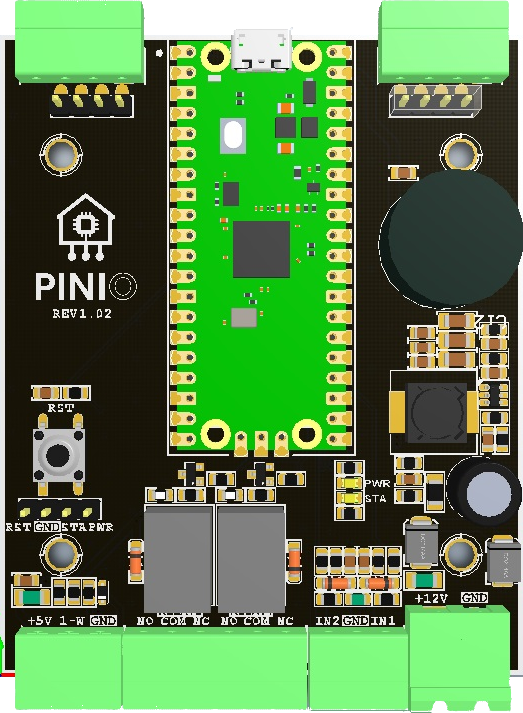
🧩 Terminal Block Layout
┌──────────────┬──────────────┬──────────────┬──────────────┬─────────┐
│    1-Wire    │   Relay 1    │   Relay 2    │    Inputs    │  Power  │
├────┬───┬─────┼────┬────┬────┼────┬────┬────┼────┬────┬────┼────┬────┤
│+5V │1W │GND  │NO  │COM │NC  │NO  │COM │NC  │IN2 │GND │IN1 │+12V│GND │
└────┴───┴─────┴────┴────┴────┴────┴────┴────┴────┴────┴────┴────┴────┘
- 1-Wire – used to connect digital sensors (e.g. DS18B20): +5V, 1W, GND
- Relay 1 / Relay 2 – relay terminals:
- NO – Normally Open
- COM – Common
- NC – Normally Closed
- Inputs – IN1 and IN2 for buttons or sensors (GND is shared for both)
- Power – +12V and GND – main power input
💡 The relays and inputs are fully independent – you can use them for separate circuits.
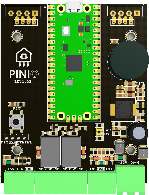
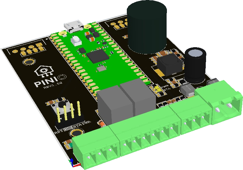
📷 Photos
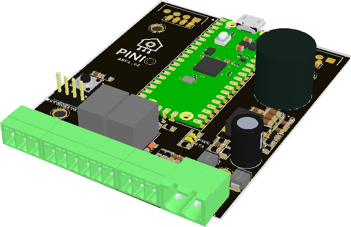
🔧 Optional (pre-soldered floating terminal blocks on the top for manual fly-wire connections)